In EE 230 (Electronics and Systems) Fall 2022, we had a small project
over a couple of weeks to design a circuit that would change what LED
was turned on based on what temperature a sensor was reading. The
challenge was that the sensor needed to turn on lights at one
temperature and turn it off again at another. The temperature sensor
output had different voltage depending on the temperature that it was
sensing. Fortunately, a year prior I had heard an upperclassmen
mention a hysteresis circuit to implement just such a function. With a
bit of research, I found a nice document describing the math and the
circuit which my lab partner and I implemented. We started our
implementation by doing the math described in the document for each of
the LEDs for their on and off conditions. Then we simulated it on an
simulator called Falstad to ensure our math was correct. Once
everything was working properly, we made the circuit on a bread board
and verified it worked as intended. We ended up struggling to get it
to work on hardware initially and solved our problems by using a
better op amp. This taught me the importance of knowing that Op-Amps
do not function as perfectly as the ideal op-amp. I really enjoyed
this project because I could use information I learned in Solar Car
and it was really cool to see it functioning properly. I also
implemented the circuit with a microcontroller as a joke because the
project description never said we explicitly had to do it analogly and
could not do it digitally, although the lab TAs shot down that plan.
Image Gallery
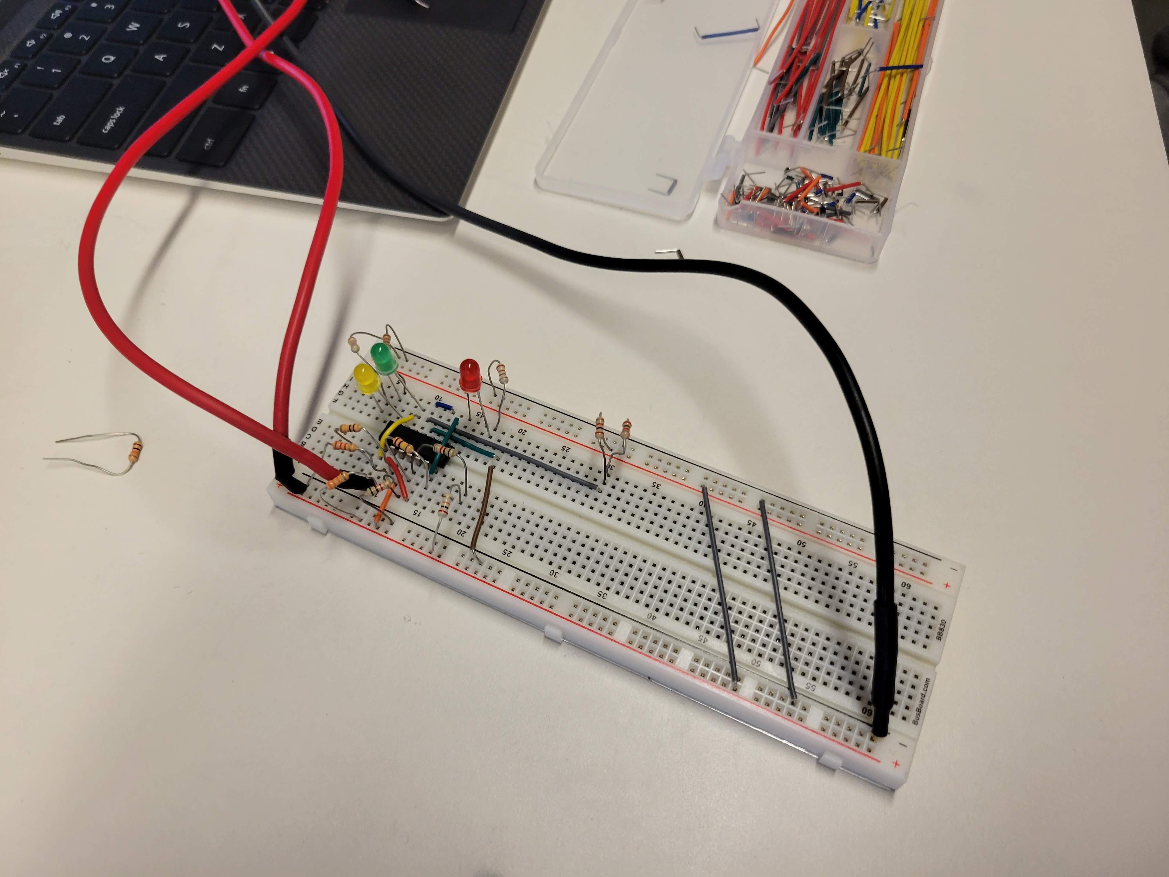 Breadboard implementation of our circuit
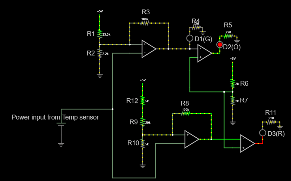 Falstad simulation of our circuit design
Project Report